|
|
|
|
Scale-Up SX Pumpers and Mixers
|
This article was written for Hydro 2003, Vancouver and put here on 3/25/03
Table of Contents
Abstract
Introduction
Figure 1
SX Pumper Characterization
Dimensionless Numbers
- Equation 1
- Equation 2
- Equation 3
Power-Flow and Head-Flow Plots
- Figure 2
- Figure 3
- Figure 4
- Figure 5
|
 |
Construction of the head-flow and power-flow plots
Examples on how to use these graphs
- Example 1
- Example 2
- Example 3
-
Example 4
Hydraulic Efficiency
-
Equation 4
-
Equation 5
- Equation 6
- Figure 6
Operating Ranges
-
Equation 7
-
Equation 8
Pilot Plants Look Different
- Example 6
-
Equation 9
- Equation 10
Designing the Pumper Stage with Multiple Impellers
- Figure 7
Scale-up of the Auxiliary Tanks
- Example 7
- Example 8
Comparison With Other Impeller Designs
Conclusions
References
Abstract
The methodology of determining the optimum SX
pumper-mixer system based on bench top, pilot, or small-scale solvent extraction
systems, is demonstrated. The design of small-scale SX-plants is different
than a full-scale plant. The difference is explained here. The use of
dimensionless parameters Nh, Nq, and Np that describe the head, flow and power
of the pumper is shown and how to use them for the scale-up. Additional
data is required to determine the optimum operating range. Applications of this methodology were used to design well known currently
operating SX plants. The emphasis on the optimization of hydraulic
efficiency will be shown on examples, including how the hydraulic efficiency is
affected when the throughput of the system goes beyond the design. Designs
of all sizes of equipment will be shown which optimize the hydraulic efficiency.
Introduction
Solvent extraction (SX) has been used to extract metals for a long time. In the late 1960s, the popular and accepted Holmes & Narver design was introduced to recover copper [1]. Design data was scarce and new plants were often designed based on past experience. In the early days of large-scale solvent extraction, it was not uncommon to find plants based on similar throughputs. The design of solvent extraction plants was an art, understood by a few. With time, four other solvent extraction designs surfaced: Davy, Bateman, Outokumpo, and Krebs. None of these companies publish enough details for engineers to design their own plants. The former all have the same mixer-settler concept: one impeller in the first chamber or tank creates the flow and initial dispersion, other impellers maintain the dispersion long enough for the mass transfer to take place, and a settling zone separates the aqueous from the organic phases (Figure 1). Krebs has reversed the order with mixing first and pumping second. |
 |
|
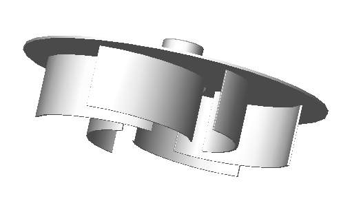
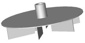
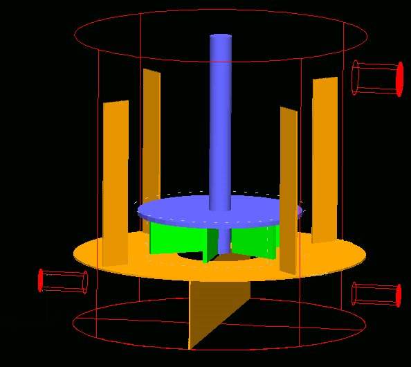
Figure 1: A mixer-settler overflow schematic showing the pumper and
auxiliary mixing stages, followed by a settler of a conventional SX-circuit.
Starting in 1995, Lightnin published several papers on their research that shed light on how to design and scale-up solvent extraction pumper and auxiliary boxes, which followed the Holmes & Narver concept and improved on the pumper design [2-6]. They published enough data so that a basic SX plant can be designed. The same concepts and rules are applicable to the other SX designs and this will be demonstrated. The optimal design has now migrated away from square boxes to cylindrical tanks, which are now used in all designs. The design principals are still the same, though.
|
|
The pumper stage must be designed to overcome the head of the system and provide the desired flow rate. It also produces the initial aqueous/organic dispersion. If too much shear is generated in obtaining these requirements, the organic and/or aqueous droplets are reduced to fines, and create entrainment problems in the settler or separator [3-6]. Open conventional systems will entrain air from the surface. Outokumpu recognizes this problem and installs surface covers to eliminate the air induction. If there is not enough shear, the mass transfer of the metal complexes will suffer, because the phases begin to separate before the settlers. In severe cases an aqueous lock around the pumper will drive up the local density near the pumper and can cause the head requirement to go up to the point that the pumper box may overflow or stop flowing.
The auxiliary stage must be designed to maintain
the initial dispersion at a minimum of extra shear. Good mixing is important with high flow, to minimize
short-circuiting and maximize contact time of the two phases. If the mixing isnt designed right, phase separation
can already occur here and cause increased head requirements on the pumper, which will restrict
the flow. Lightnin uses up-pumping
axial hydrofoils for this purpose, while Outokumpu uses the Spirok and Krebs
uses a pitched bladed turbine.
Understanding how to design SX pumpers and
auxiliaries helps to explain why optimized pilot plants look different from
their full-scale counterparts. The following scale-up technique is applicable to all of the SX designs. It has been proven on 57 installations in 1997 and many more since then [6].
Click this title to continue with this article.
|
 |
|
|